Transparent Stereoscopic Display and Application
N. Ranieri, H. Seifert, M. GrossProceedings of SPIE 9011 (San Francisco, USA, February 3-6, 2014), pp. 90110P
Abstract
Augmented reality has become important to our society as it can enrich the actual world with virtual information. Transparent screens offer one possibility to overlay rendered scenes with the environment, acting both as display and window. In this work, we review existing transparent back-projection screens for the use with active and passive stereo. Advantages and limitations are described and, based on these insights, a passive stereoscopic system using an anisotropic back-projection foil is proposed. To increase realism, we adapt rendered content to the viewer's position using a Kinect tracking system, which adds motion parallax to the binocular cues. A technique well known in control engineering is used to decrease latency and increase frequency of the tracker. Our transparent stereoscopic display prototype provides immersive viewing experience and is suitable for many augmented reality applications.
Overview
In our society of the digital age, information has become one of the most important resources.
Data is acquired anytime and everywhere, processed, stored or played back to users, who often are over-strained by the mass of information.
With augmented reality (AR), efforts have been made to embed such information into the real world to make them easier accessible and readable.
Example given, head mounted displays (HMD) can overlay an image with a user's field of view, providing additional information to what he is looking at.
Prominent example is the Google Glass, but many others exist.
Although being compactly build, the additional hardware required on the glasses often makes them cumbersome to wear.
For a different kind of applications, Samsung uses a light-box with a transparent liquid crystal display (LCD) in front of it to show additional information for a product exposed in the box.
Similarly, LG uses a transparent LCD as door of a fridge to inform a user about content while giving clear sight of the food inside.
However, transparent LCDs are not self-emissive, transmit only 33% of the light through the color filters and absorb another 50% in the polarizer.
Hence, extremely bright background is needed to account for the resulting transparency of usually less than 17%, which narrows the area of application. Transparent OLED, a promising alternative, are self-emissive but also could not achieve sufficient transparency so far.
Sun Innovations propose a self-emissive solution with high transparency: A fluorescent film displays content when activated by a galvonomic blue-ray laser scanner.
The screen can be used in environments with any brightness, but so far it has been used to show 2D content only.
One problem of such transparent 3D systems is how to align virtual content with the real world.
This can be achieved by tracking a viewer's eye position relative to the screen and adapting the rendered content accordingly.
Though, tracking devices usually suffer from low refresh rates and high latency.
These issues can be overcome using a Kalman filter and prediction, which has been successfully done for human motion and opaque 3D screens in previous work.
But transparent 3D displays demand a much higher accuracy and lower latency, as the viewer can see and compare real objects and virtual content at the same time with respect to their movement.
Thus, these existing approaches have to be re-evaluated to see whether the quality still can achieve an immersive experience.
In this work, we assess both isotropic and anisotropic transparent back-projection technologies for the use in combination with passive and active shutter glasses.
Based on the derived insights, we propose and build a transparent stereoscopic 3D system for augmented reality.
Next, we apply Kalman filters and prediction to a Kinect tracker to verify that it can be used to provide proper perspective cues and motion parallax on a transparent stereoscopic screen.
Results and a discussion conclude our work.
Results
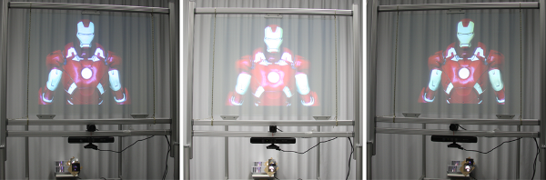
Figure 2 shows three perspectives of a synthetic scene rendered on our physical prototype.
The left image shows the view of the left eye from the left side.
Similarly, the right image shows the view of the right eye from the other side.
The images were captured on a Canon EOS-1D Mark III with a linear polarizer in front to simulate the effect of the polarized glasses.
Both images show as well the image separation and crosstalk as the motion parallax when moving to different positions.
The center image shows a center position with no filter in front of the camera. Hence, both views are overlaid and the captured image is brighter.
The rainbow effect, common to anisotropic back-projection screens, is not visible in the photos and only barely visible by eye.
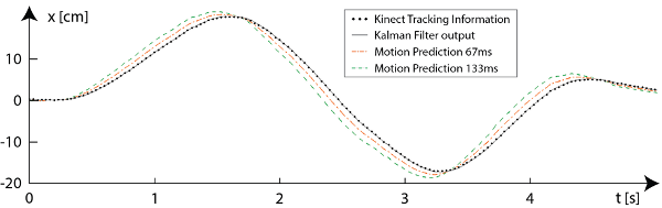
Quality of the improved tracking results are shown in Figure 3. The plots compare predicted, up-sampled and filtered signals with different prediction time (dashed lines) with the measured signal (dotted line).
The predicted signal decreases in quality with increasing prediction time.
Our system is able to provide motion parallax for slow viewer motion.
If the viewer moves fast, further improvements or a better tracker would be required, as the prediction time of 67ms becomes too large.